
Schematic
Full Schematic
Section titled “Full Schematic”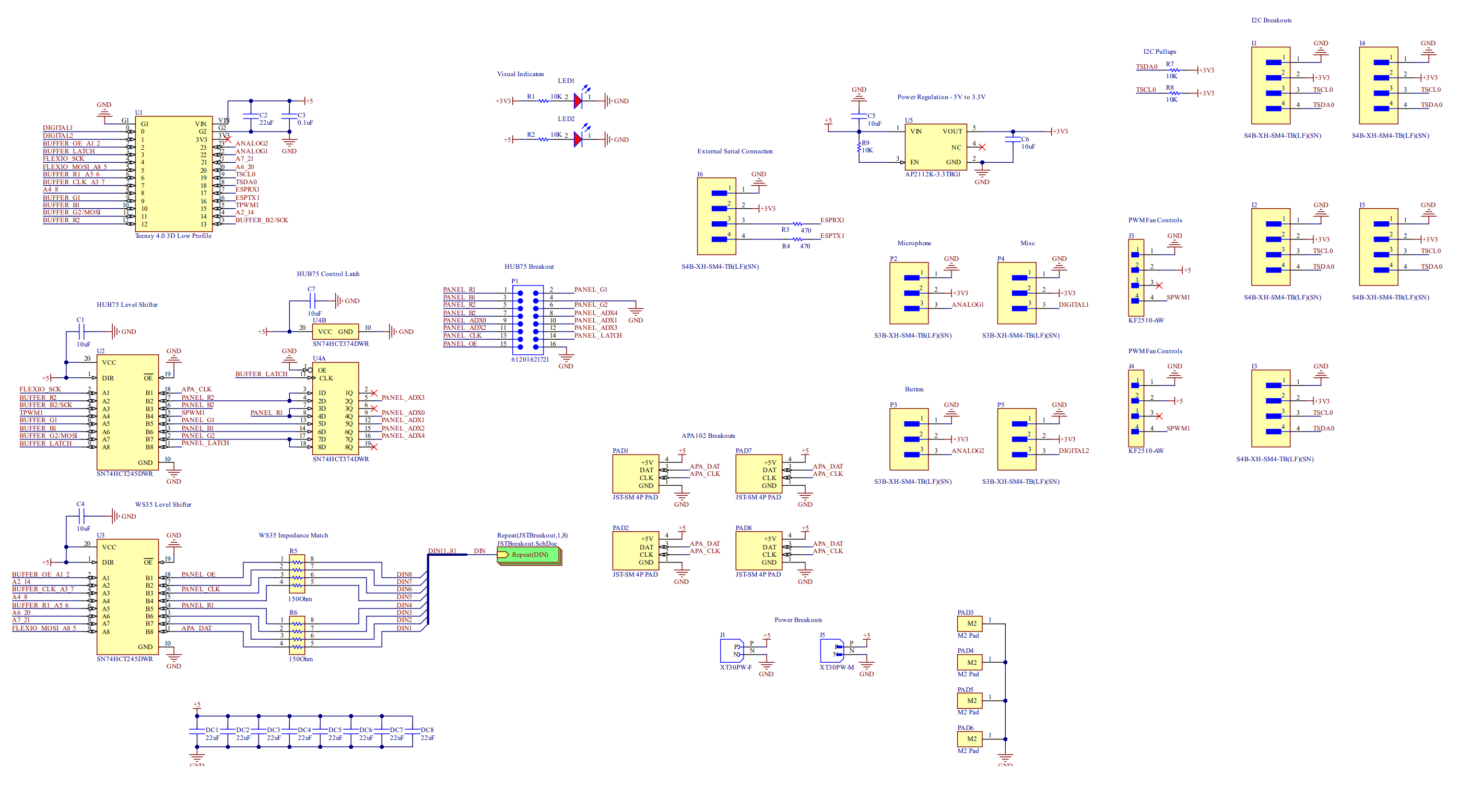
Teensy Pinout
Section titled “Teensy Pinout”The Teensy 4.0 is the central microcontroller with the following pin assignments:
| Pin | Function |
|---|---|
| 0 | DIGITAL1 |
| 1 | DIGITAL2 |
| 2 | BUFFER_OE_A1_2 |
| 3 | BUFFER_LATCH |
| 4 | FLEXIO_SCK |
| 5 | FLEXIO_MOSI_A8_5 |
| 6 | BUFFER_R1_A5_6 |
| 7 | BUFFER_CLK_A3_7 |
| 8 | A4_8 |
| 9 | BUFFER_G1 |
| 10 | BUFFER_B1 |
| 11 | BUFFER_G2/MOSI |
| 12 | BUFFER_R2 |
| 13 | BUFFER_B2/SCK |
| 14 | A2_14 |
| 15 | TPWM1 |
| 16 | ESPTX1 |
| 17 | ESPRX1 |
| 18 | TSDA0 |
| 19 | TSCL0 |
| 20 | A6_20 |
| 21 | A7_21 |
| 22 | ANALOG1 |
| 23 | ANALOG2 |
Logic Handling HUB75/APA102/WS2812
Section titled “Logic Handling HUB75/APA102/WS2812”The HUB75 level shifter uses SN74HCT245DWR chips to convert 3.3V logic to 5V for the LED panels. The WS2812 level shifter provides signal conditioning for individually addressable LED strips with 150Ω impedance matching resistors.
Power Handling and Voltage Regulation
Section titled “Power Handling and Voltage Regulation”The power regulation circuit uses an AP2112K-3.3 regulator to step down from 5V to 3.3V for the Teensy and logic circuits. Decoupling capacitors (22µF and 0.1µF) ensure stable power delivery.
Visual indicators include:
- LED1: 3.3V power indicator (10K resistor)
- LED2: 5V power indicator (10K resistor)
Sensors and Inputs
Section titled “Sensors and Inputs”The board provides several input connectors:
Microphone (P2):
- Pin 1: GND
- Pin 2: 3.3V
- Pin 3: ANALOG1
Misc Input (P4):
- Pin 1: GND
- Pin 2: 3.3V
- Pin 3: DIGITAL1
Button Inputs (P3, P5):
- Pin 1: GND
- Pin 2: 3.3V
- Pin 3: ANALOG2 / DIGITAL2
I2C and UART Communication
Section titled “I2C and UART Communication”I2C Breakouts (I1-I5): All five I2C ports share the same pinout:
- Pin 1: GND
- Pin 2: 3.3V
- Pin 3: TSCL0 (Clock)
- Pin 4: TSDA0 (Data)
I2C pull-up resistors (10K) are integrated on the board.
External Serial Connection (I6):
- Pin 1: GND
- Pin 2: 3.3V
- Pin 3: ESPRX1 (470Ω inline resistor)
- Pin 4: ESPTX1 (470Ω inline resistor)
PWM Fan Control
Section titled “PWM Fan Control”Two PWM fan control headers (J3, J4) use KF2510-AW connectors:
- Pin 1: GND
- Pin 2: GND
- Pin 3: +5V
- Pin 4: SPWM1
Mounting Points
Section titled “Mounting Points”Four M2 mounting pads (PAD3-PAD6) are provided for secure mounting of the controller board.